Carbon panel FEA & layup study
How we validate a laminate: load cases, stress results and a ply schedule tuned for stiffness and weight.
- Industry
- [e.g. Drones / UAV]
- Services
- FEA & layup
- Material
- Carbon fiber [resin system]
- Process
- [Prepreg / infusion / wet layup]
- Timeline
- [e.g. 1 week]
The challenge
Show how a carbon part can be checked for strength and stiffness, and how changing the ply orientation changes the result, before any tooling is made.
[Describe the part, its load cases and the targets it had to meet.]
What we did
Stage 1
Load cases & model
We defined how the part is supported and loaded, then built the finite element model.
[Load cases and assumptions used.]
Stage 2
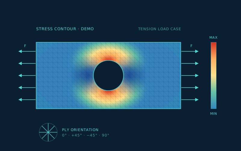
Stress & deflection results
We identified where stress concentrates and how much the part deflects under each load case.
[Key results.]
Stage 3
Layup iterations & ply schedule
We compared layups and settled on a ply count and orientation that meets the targets at the lowest weight.
[Final layup, e.g. [0/±45/90]s, and why.]
The result
[Outcome with numbers if you have them, e.g. stiffness gained or weight saved versus the starting layup.]
Your part next?
Have a similar part? Get a free feasibility check.
Send your CAD and get a risk report within 48 hours. No cost, no obligation.